Engine Tech Series - Mopar Rocker Arm Geometry, Part 1
A good read for everyone, not just Mopar enthusiasts!
Mike Beachel
Owner, B³ Racing Engines
The objective of this article is to thoroughly explain the importance of proper valvetrain geometry, and to address the mountains of misinformation and detrimental advice given on this subject, especially to the Mopar crowd.
This article may get lengthy, detailed, and deep, but stick with us because the goal is to have you informed with logical, common-sense information that will help you get the most out of your performance engine.
First, let’s start with some history. You can’t know where you are going if you don’t know where you came from.
Geometry, in its basic definition, is a branch of mathematics that deals with the measurement, properties, and relationships of points, lines, angles, surfaces, and solids. [1] This field of knowledge dealing with spatial relationships was revolutionized by Euclid, c.300 BC, who is considered the “Father of Geometry”. [2]
Another form of mathematics that is used extensively in valvetrain setup is Trigonometry. Trigonometry is the study of the properties of triangles and trigonometric functions and of their applications. [1] Hipparchus, c.190 BC-c.120BC, is credited with founding trigonometry, and is considered the “Father of Trigonometry”. [2]
Any manufacturer, author, racer, salesman, or other who gives advice or direction contrary to these mathematical principles that have been around for more than 2000 years, is simply incorrect and misleading, whether by uninformed opinion or by design to promote or sell a product.
Let’s start cutting through some of the fog and mystery surrounding proper valvetrain geometry.
The purpose of the rocker arm is to transmit the motion of the camshaft to the valve at a specific ratio, i.e. 1.5:1. The path of motion changes as it is transmitted from camshaft to valve. The camshaft has a rotational motion that is converted to linear motion into the tappet and pushrod. That linear motion is then converted back to a rotational motion in the rocker arm, and again becomes linear in the valve.
Everyone knows that the shortest distance between two points is a straight line. This isn’t a problem with the linear motions as they will always be in a straight line unless angularity is introduced into one of the linear motions, i.e. Small Block Mopar pushrod angle. Then motion is no longer truly linear and efficiency is lost. However, the rotational motions sweep through an arc, losing the efficiency that would be present in straight line motion. The key to optimal valvetrain operation is having geometry that reduces the efficiency losses, through these rotational motions, to the bare minimum possible, within the design parameters of the rocker arm and camshaft.
Now that we have covered the basics of valvetrain motion, we need to address some of the bad information that has been passed around for the past 50 years or so.
First, we’ll start off with the idea that on a roller rocker, the roller needs to sit in the center of the valve stem to have correct geometry. While, in a sense, this may be a form of geometry (roller point to valve tip point), it is in no way related to efficient valvetrain operation. This is simply a function of fulcrum length (the distance from the shaft centerline to the roller centerline), and can be manipulated by moving the shaft either closer, or further away from the valve stem. While it makes sense to have the most contact area between the roller and the valve stem, it is often given priority over reduced sweep. This is why many times a set of rockers that center the roller nicely when the valve is on the seat, will just about roll off the end of the valve when going through the lift cycle. It is not uncommon for rockers installed this way to have over .100” sweep, when they should only have .030” sweep. That is over 3 times the inefficiency of a properly set up valvetrain. Most budget (not Jesel or T&D) roller rockers are just bolted on and have this huge loss of efficiency. One company recommends installing longer valves to have correct geometry (roller centered on valve tip). This recommendation actually makes the geometry even less efficient and causes more sweep. They have to know better!
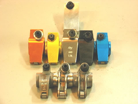
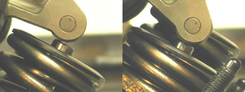
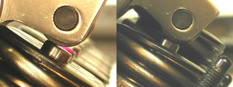
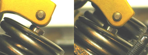
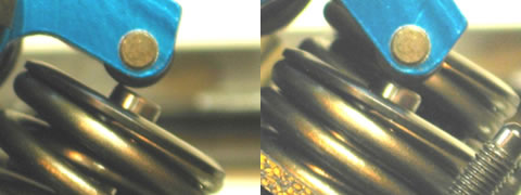
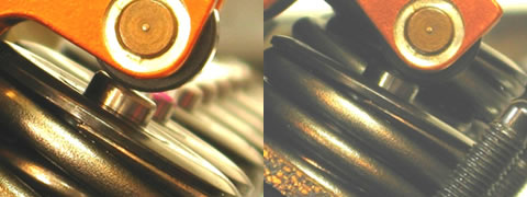
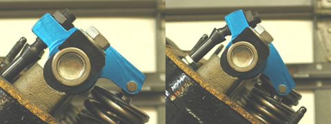
Here are some examples of various fulcrum lengths, evidenced by roller placement on the valve tip, and sweep at full lift.
All photos were taken on the engine shown, and in the same rocker location for a true comparison.
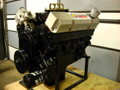
383 Bracket Engine
PRW Stainless Steel 1.7

ProComp Stainless Steel 1.5
RAS 440 Max Stainless Steel 1.5
PRW Aluminum 1.6
Crane Aluminum 1.6
CAT Aluminum 1.7
Proform Aluminum 1.6
Harland Sharp Aluminum 1.6
B³RE Aluminum Prototype 1.6
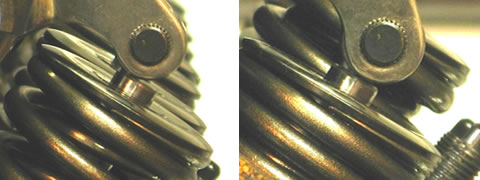
As you can see, fulcrum lengths run the gamut with some being so short that they barely reach the valve tip, while others are so long that they almost roll off the valve at full lift. They all have too much sweep, and would be very inefficient if just bolted to the head stands. Before wrapping up this segment, take a look at the next rocker photos and compare them to the previous ones of the same rocker.
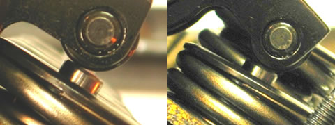
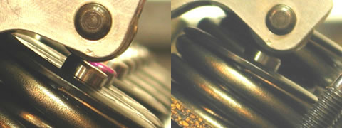
Proform Aluminum 1.6
The roller is more closely centered on the valve stem AND the sweep was reduced from .096” to .031”. That is a 309% reduction in wasted motion! Think about this a while, and stay tuned for Part 2 of our rocker geometry tech article. There is much more good information to come!
[1] Merriam-Webster Collegiate Dictionary 10th Edition
[2] Wikipedia-Additional references at www.wikipedia.com