Engine Tech Series - Mopar Rocker Arm Geometry, Part 4
Mike Beachel
Owner, B³ Racing Engines
I know what you’re thinking. “Finally, Mike decided to get off the couch and shuffle to the computer to write another tech article.” An understandable suspicion, because this article is long overdue. Trust me though, we have been busy serving performance enthusiasts like you with parts and services, and we are grateful for the opportunity to do so.
In the previous article I mentioned getting into the pushrod side of valvetrain geometry, and that is the focus of this article. This is the one area where problems are not easily corrected primarily because the adjuster location is designed into the rocker arm by the manufacturer, and this design is generally a compromise based on other considerations such as cost, materials, and manufacturability. Just like the valve side of rocker geometry, the pushrod side should have the least amount of sweep possible to maximize valvetrain efficiency. Unfortunately, I have yet to see a single shaft Mopar roller rocker system that has the proper adjuster location. There may be something like that out there, but I haven’t had my hands on a set.
The sweep is found at the centerline of the ball pivot where the pushrod and rocker meet, whether it be on the end of the pushrod, or the end of the adjuster. Most of the budget aluminum roller rockers carry over the ball type adjuster from the OEM ductile iron rockers -- which didn’t have a roller tip, by the way. As mentioned in a previous article, adding the roller changes the geometry points, and the adjuster side is not immune to those changes. We have found that using a ball style adjuster is a bad idea with a roller rocker. It is impossible to get the pivot point high enough for proper pushrod side geometry, without making the crown of the rocker so tall that the moment of inertia becomes intolerably high. There is simply too much weight for stable valvetrain operation. For this reason, as well as the pressure-fed oiling, we prefer a cup style adjuster.
The height of the pivot point isn’t the only problem with the adjuster. The angle of the adjuster is incorrect as well. We have found one budget rocker brand that has the correct angle, but uses the ball style adjuster, so the sweep is far too extreme. The rocker could be modified to use a cup style, but there are other issues we have with the design of this brand that makes it impractical to go through the trouble of changing it. Most rockers on the market have an adjuster angle that is off by 10 degrees or more. When the rocker is just bolted to the stands, the angle looks OK, but we already know that a roller rocker cannot be just bolted on and have proper geometry. Once the shaft is raised to correct the fulcrum point, the adjuster is now at a greater angle than it should be. As the adjuster sweeps outward, the pivot point moves away from the centerline of the rocker shaft, and reduces the effective ratio. We have seen net lift losses of .030” and more due to the inefficiencies from an incorrect adjuster angle.
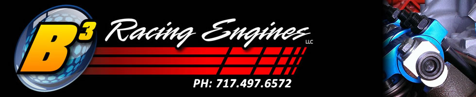
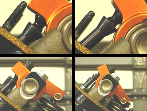
Check out some photos showing the excessive angles from an incorrect adjuster location. We will show the pictures with uncorrected valve side geometry, on the seat and full lift, and then after correction, also on the seat and full lift. The excess angularity will be obvious.
RAS 440 Max
Crane
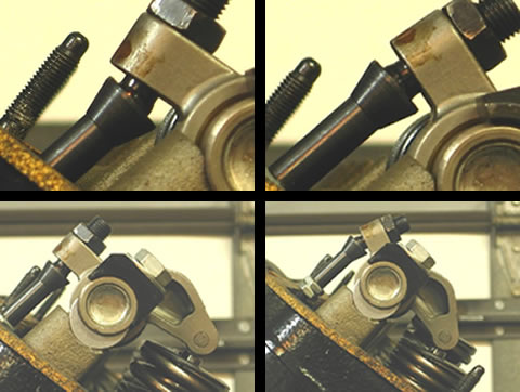
PRW
Harland Sharp
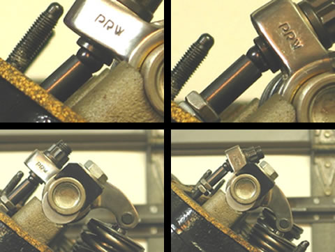
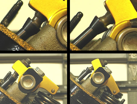
PRW Stainless
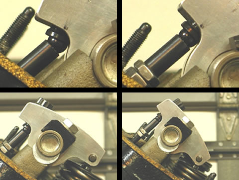
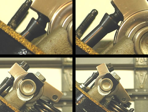
B3RE Prototype
Notice how the angles look better on all the rockers before the shaft was raised, with the exception of the B³RE Prototype. Our prototype is the only one that looks, and is, correct after the fulcrum was moved to the proper position.
Now, you may be asking yourself, “Why would I raise the shaft if it is going to angle the adjuster too much”? Well, because the pushrod side of the geometry has more to do with losses in lift and ratio than it does with instability. What breaks parts is when the valvetrain becomes unstable, which results in valve float. The hammering on the valvetrain overstresses the parts and the weakest point fails first. That will have more to do with adjuster breakage than the side loading from the excess angularity. So, getting the valve side correct reduces the stresses incurred on the rest of the valvetrain drastically reducing the potential for breakage.
The best approach to the adjuster problem, once the fulcrum height is correct, is to run the longest pushrod possible. It will reduce the sweep of the pushrod, reduce ratio loss, and also reduce the leverage the pushrod places on the adjuster when the angles are at their highest. This is another good reason to use a cup style adjuster, because it will not need to stick out the bottom of the rocker body as far as a ball style and still have proper oiling. A compromise for sure, but without a properly designed rocker, there isn’t much else that can be done here.
Talking about adjusters and pushrods reminds me of another problem I run into when talking geometry to some Mopar guys and girls. Some are choosing pushrod length based on max lift numbers, or centering the sweep on the valve tip. This is entirely incorrect, and will result in a very inefficient and unstable valvetrain. I would love to get into that right now, but this article is already lengthy so I will address it in a future article.
I appreciate all of the feedback we have been getting from the tech series, and look forward to getting more. I’ll write the next article as soon as I can. Thanks for your patience, and stay tuned for Part 5.